Electrical
On any restoration, the electrical system must not be neglected. Just like the brake lines and other parts, it is extremely important to the safety and operation of the car. I found it interesting that even though I was told it was a cigarette that torched this convertible while it was parked at a mall, I noticed the alternator had been replaced by a newer style one, and that the power wire off that system ran through the firewall with no protection, and was totally destroyed, there was no insulation left on the wire for 12 inches on either side of the firewall, unlike the other burned wires. Hmmmm...
Any information presented here is only for your amusement, any modifications to your car are done at your own risk. I am not responsible for any problems or damage you may have from using this information!
First thing on the list is the top operation. GM found it acceptable to run
the full power for the A-Body convertible top motor through the small switch in the
dash. This may have worked when everything was new, but as things wear and need more
power to run the system, it tends to overheat this switch and its tiny contacts.
I have heard of many switch failures, and since they no longer make this switch,
it is something to be avoided. I have also heard of them getting very hot during
operation, and even starting fires...this is all in the three years since
I bought this car. No doubt there are other factors involved, but I still decided
that some sort of relay system to transfer the main power would be a better solution.
The only requirements would be no cutting of the factory wires, and it must be hidden.
This is what I came up with. First the factory wiring diagram. Note the full power
feeds through the switch off the 40amp circuit breaker terminal. There is a forward
switch harness which connects to the mid car harness right near the fuseblock. The
relays will be located somewhere in this location. The aft harness is actually the
leads off the top motor/pump.
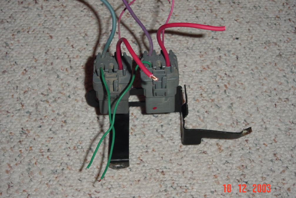
These are the relays I decided to use. They were removed from a mid 90's Grand AM GT at the wreckers. The relays are located in the upper aft passenger side area of the engine compartment. There are four of them, and they come on a small bracket. I bought everything for $4.00. The relays have weatherpack connectors on them, and I should have cut longer lengths of wiring off the car as I could have avoided making up new terminals at both ends. These are Bosch 40amp relays, and plug into the top part of the connector. Even the wires are close in color....I moved the wires around to simulate roughly how it would be set up in the car. Bracket will be trimmed to make mounting easier.
Also, note that some earlier Grand Am's had the relays mounted into a fuse type plastic block, and the relays themselves have blade type connectors (instead of the weatherpack setup) which you may prefer.
Here the bracket has been trimmed to mount two relays, and also a third separate
mounting tab.

This is the final wiring diagram, your feel free to pick the colors you want to use. Note that I have used one of GM's one into three power feed splitters for main power, this will work well for my car as there will be one terminal for each relay, plus the third connection for my power window harness. The original switch harness will need the plastic connector changed so it can plug into a different terminal for the signal power. You will also need a couple of the two wire connectors from GM to make up the ends of the relay harness that will plug into the factory harness. At this point in time, I have not decided where to mount the relays themselves, I will spend some time with that once I get the car back from the resto shop.
Note the diagram is not to scale.

Dec 18, 2003
Somebody on the V8 buick message board suggested mounting the relays in the trunk. This would prevent running high current through most of the original harness under carpet, and makes sense. Basically you would just move the connectors to the back split in the harness, then run one large power feed (10 or 12 gauge) to the back, have it split back there for each relay. I am more concerned with power going through the switch than the wires themselves, but there is a lot of space under the rear seat support and the whole setup could be hidden inside that without too much trouble.
NAPA sells the GM style terminals needed to make up all the connections. P/N for
the female is 725147 and P/N for the male is 725145....these are 14 to 18 gauge brass
terminals that will snap properly into the factory GM harness connectors. Make sure
you get a proper crimping tool, loose connections can be dangerous.
Dec 21/2003
Several people have now done this modification with great success! Running the power feed wire has been done by feeding it back through the underfloor harness, and one person ran 6 gauge wire under the car and up through the aft floor so he could also power his amps, these relays and various other devices through a terminal strip. Having the relays at the back works well, as it keeps the leads down and also everything is easily hidden in the rear seat support. I have changed the diagram above to show mounting the relays in the rear seat area as that seems to be the best way for now.
Jan 15, 2004
With the driveline basically complete, and the body almost complete, attention turns to the small details. While most of the wiring harnesses I have now for this car are complete and in excellent condition, the one that is really messed up is the engine harness. Since I am converting the car to a 455 I need to use a 455 harness as the 350 one (good shape) will not physically fit.
Look at this mess! In the 30+ years since it was installed in a car, the alternator connector has been changed to internal regulator style (with butt splices), the TH400 kickdown wire has been simply cut off, several wires have been added, and three more have been spliced together in an apparent attempt to get power to some system. And of course, the original stuff left has major wear and/or damage. And on top of all that, it is for an a/c car so has an extra connector that I won't need. Oh yes, don't forget the sticky residue from the mandatory black tape wrap job it had.

So at this point I have a couple options. The easiest is to simply order up a new engine harness from one of the wire companies (M&H comes to mind). I have no experience with these harnesses or their quality, and they are not cheap.
The other option is to rebuild it myself. This is not hard to do, as I have the tools and skill to do it. The problem is obtaining the needed wire and connectors. You can buy most colors of wire in most gauges, BUT many of the wires in this harness have a colored stripe on them and I don't know if you can even purchase wire like that. Second is the connectors, in this case the only one really needed is the TH 400 two pin connector that plugs into the transmission. You can buy it separately, but it comes with molded in wires (wrong color) and if you have to splice it into the harness, doesn't that defeat the purpose of rewiring??
It needs to work and look correct, as these are the only wires you will see once the car is completed. A failure in this harness will leave you stranded.
Aug 25, 2004
See my reproduction page for the engine harness I bought. Its excellent, all the correct colors, clips and terminals. Cheaper than I could have made it up too, given that I needed most of the harness connectors and wire. It's nice to know if necessary, you can buy almost any harness you will need for one of these cars now.
Also, there has been a change in my plan for the power top relay setup. I discovered
that every power window equipped car also has a 10 gauge orange pre-made wire that
takes power off the window harness and ends about where the front seat is located,
this wire would be for the power seat option if equipped. My car does not have a
power seat, so I will make up another 10 gauge wire and connect it to this one to
carry the main power back to the top relays. This also eliminates the need for the
1 to 3 splitter, since the top harness plugs into the main power connection on the
fuseblock but also has provision for one more power accessory to plug in. So the
original top harness now becomes the signal harness for the relays (still plugged into original spot), the extra provision
off the top harness will power the window harness and from that the power seat wire
will supply the main power for the top relays. This will also allow easy return to
stock (just unplug and remove wiring/relays, then reconnect the original connectors
at top pump). This is the final diagram for my car:

The rest of the harnesses I've found were in very good shape and only a few wires needed repair
or replacement. They were all re-taped with the proper non adhesive wrapping tape.
DO NOT use black tape, it makes a mess and won't allow wires to flex as they might
need to once installed.
Dec 13,2004
As the car reaches final completion, it is time to replace the alternator. I ordered one and went to pick it up. It was an internally regulated one so obviously incorrect. The part number was checked and found to be in error. Another was ordered, and when it showed up I opened the box and saw the new style case again. WTF?? So I came home and started doing some research. Interesting stuff as I noticed the 72 service manual I have shows the new style case AND the external regulator. Turns out 72 was a transition year and all the alternators on these cars were the newer style case, yet still used the square connector (internally regulated uses a flat connector) and external voltage regulator.
There was one internally regulated alternator in 72, the 80amp large car version. It may have been used in cop car Skylarks as well, and the assembly manual does show an 80 amp install in the A-body cars but does not specify which models.
Only two are listed for use on the A-body Buick cars. P/N 1102449 is the 37amp version, P/N 1102448 is the 55amp (optional version). Both are new case style, square plug, externally regulated.
Just for a laugh, I went and checked the box of old alternators I keep for cores. Several had come from the trunk of this convertible and sure enough, there was the correct P/N alternator, date coded Aug 14, 1971, just weeks before my car was built. I almost threw it away 5 years ago as I had thought at the time it was an internally regulated alternator and thus no good for this project!
I will likely update the internals to 55amp. If you look at the pic you can see a letter "C" stamped on the aft case housing (far right side of alt), obviously a code of some sort but still researching it at this time. Also, I would have thought a power window/power top convertible would have had the higher amp alternator, but the only cars to get the 55amp alternator were the a/c equipped machines.

Feb 1,2006
I never thought battery cables would be such a pain!! All the local parts places stock basic cheap black cables, nobody has red and nobody has the larger gauge wire either. It also appears that reproductions aren't available either as the 72 cars used side post batteries, all I can find is up to 71. I am researching, hopefully can find something decent. GM actually has the correct negative wire, but they have a new style huge black plastic housing over the swaged terminals on the battery, it looks out of place for sure and is expensive to boot.
Here is a pic of two original 72 cables, both negative. You can plainly see the 455 cars got a larger cable (#2 gauge), both should have the secondary wire too but the one is broken off.

Of course, if you had a Chevelle or a Camaro you could simply order the cables you need, ready to go. I am currently hunting a correct looking positive cable for this project, looks like the best way at this point might be to by one for a big block Chevelle and then trim the starter end to fit (assuming the length is actually long enough). I ordered a discontinued NOS Buick positive cable from a specialty shop one and it is correct but molded in black as well. I'd like red. So the search goes on, I'd like to get this sorted out fast as I need to get power on this car to check out the electrical items. Will post lengths etc once its all finalized.
Updated Feb 22/2006
After I updated this page last time, I was pretty sure that I still had an original positive cable off a 455 car here somewhere. Turned out it was still bolted onto my 72 GS 455 coupe sitting on the farm. Pulled it off and confirmed it is the original cable to that car (assembly manual lists that p/n and letter code as cable to install in that car). That is helpful since I now have a correct cable to get measurements from should I need to have one made up. Buick also had a plastic block attached onto their cables, this block would slide into a bracket on the side of the engine and also had a slot for the starter wires to pass though as well, this kept everything separated and protected. Nobody makes these blocks so the search is on for one of those too.
A discussion on the V8 board resulted in the theory that the NPD battery cable p/ns for the chevelles actually have the cable length in them, hope we're right because I ordered a set based on that. Even if the cable is black but the end is red I'd be ok with that. We'll know in a week.
Pic shows both pos and neg cables from a early Oct 71 built GS 455 from the Fremont plant. It looks like all 72's would have these cables, and 71 big block machines built June 71 and after as well (assembly manual has revision to drawing dated June 29, 1971-I am assuming this the switch to sidepost cables). What a PITA this has been!! I'd like to get power onto this car soon.
So 72 cars all used sidepost batteries. On the big block machines the negative cable is 26.5" long center to center #2 gauge with a 13" secondary ground to the fender, the ends are typical flat terminal, entire cable is black. The positive cable is 45" long center to the edge of the starter terminal (which bends at 90 degrees so if bent flat it would be about 46" center to center) #2 gauge, end is special starter terminal, entire cable is red with black plastic block about 6" from the starter end, and also a 16" long fabric protective sleeve that started about 6" from the battery terminal and was held in place with one wire clip about midway.

March 7, 2006
Cables showed up from NPD. Good news, bad news. Our theory was incorrect, the C-2340-46 turned out to be 42" center to center, but it does fit (currently don't have it going through the factory style block so that may upset things some). Looks good, so I got my red battery terminal anyway. Talking to M&H about making up correct red cables, might still do that too (I need another one and know others in need as well).
Ordered the negative cable for length, totally forgot smaller engines got smaller wires so although negative cable is correct length, it is not the right gauge so I won't use it. I will keep it though as its a dead match to the original 350 cable should I go back that way (NPD C-2341-28). I could use the NOS positive cable as it is completely black and has secondary lead, hate to cut it up though. Not a big deal, all the cables now are black so won't be hard to find correct one and I still have decent original to use just to put power onto car.
More than I ever wanted to know, thats for sure!
March 16, 2006
Instrument cluster assy installed (see final assembly page). Before that could be done though I had to change a few things on my replacement 72 Skylark harness to make it work properly. First one is to convert the harness for operation with the Rally gauge package (oil pressure, coolant temp and fuel gauges). The Skylarks almost all got dummy lights.
Its pretty easy to do, GM actually had a small harness that installed between the gauge pins and the wiring harness, this did the conversion. I have one, but who needs an extra 5 " of harness right behind the gauges, and also it is another set of connections that can give you grief. It is a simple matter to remove the wires from the connector and change their ports, this will be all you need to do and is much cleaner. A small screwdriver inserted into the front of the connector (in the small slots just to the RH side of each opening) can be used to bend the retaining tab flat so you can remove the wires. Once removed, make sure to bend the tab back up slightly so it will catch again once re-inserted. Here is a pic of the connector before (LH side, non rally gauge) and RH side of the picture after moving wires for rally gauge setup. Note the black wire is no longer used at all. Fold it over and tape. Also note there is a separate ground wire in the harness that connects to a separate ground tab on the gauge cluster. I did not show that for clarity. From left to right, once modified you want green/dark brown/blank area/pink/tan with white tracer/dark blue/tan/empty slot/gray.

I also needed to add the tach wire. This is a simple task as GM simply ran it alongside the main harness right out to the coil, so its a simple matter to add the correct brown wire. GM used a connector right at the firewall for ease of install.
Also, I received a call from a company who is willing to make my battery cables, including the correct all red cable. So I ordered another set and they will be available for purchase and possibly end up in their catalog. The problem is the plastic block, they can't make the cables with the plastic block as they have no source for that and so the cable won't technically be complete. It can be added by owners after the fact though or put on before the starter terminal crimp. Seems like a lot of work to make my incorrectly powered car as authentic as possible.
Anyway, power was put on and nothing fried. So far so good, one issue was dash light not working which turned out to be the bulb socket. I had to pull dash assy partway out to replace but all is well. Checked all the lights and systems I could. I always use manual gauges on engine run, then compare to what the rally gauges say, this way they are somewhat calibrated. Aftermarket gauges look like crap in a restored car IMHO.

March 19, 2006
Installed all the wiring for the CD player and rear speakers. Everything is soldered and double shrink wrapped. I like these new decks as they finally got smart and have one connector on the back so you can wire the whole mess up and then simply plug in the stereo and check it for operation. You can also take it out easily as well for shows and tuck the connector under the aft edge of the forward carpet and its hidden. This deck also has pre-outs at the back for a subwoofer, Clarion makes an underseat subwoofer that would work well. Again, easily removed for shows. Wireless remote means I will be able to run the stereo without even seeing it, although I find the only functions I ever use are skip forward or mute.

March 28, 2006
Built up and tested the top relay installation today. Hardest part of that was finding the correct relay terminals. NAPA p/n 725157 were the ones I used. The power seat feed was connected (via GM style connector of course) to a new 10 gauge wire which runs to the back. The factory top harness now connects to the signal side of the relays, and I made up new wires to connect the relays to the factory harness and motor, again via GM style connectors. ALL connectors were both crimped and soldered for safety, there is some big power going through here. Also, before connecting anything up the whole system was tested for correct operation. Hate to have the car burn again. I used an old harness to find most of the shorter wires needed (except main power feed which is new), tried to use the factory colors for up and down sides which will help should it need troubleshooting.

This is where I decided to mount the relays. Looks kinda odd being mounted at an angle but that simply gives the best access. This position allows easy access by either lifting the compartment bag (not installed until top goes on) from the trunk or from the front with the rear seat removed. There is lots of room, it allowed me to use some pre-crimped wires on the relays, and its close to the factory wiring harness entry point.
Nothing was cut, the new harness was made to fit the original connectors. The original wiring can be plugged back together and the whole thing back to stock in less than 10 minutes.
Note the 6x9's, you can see they will be useless with the top down and the boot on, but with the top up they should be ok. Will start with the factory positions and modify from there. They are tight in there but fit with about 1/8" clearance. I get enough noise at work, no need for a pounding stereo. Note the color of the speakers :)

March 30, 2006
Well after a lot of false leads and wrong parts, finally got my authentic battery cables, thanks to M&H Electric Fabricators. They made them to my specs, which I pulled off the original cables. We never discussed it so imagine my surprise when they showed up stamped with the correct p/n as per the originals. Now that is service!! The pics show the M&H part numbers on the tag, if you order the postive one, make sure to specify the red or black cable (their drawings show black cable, my orig was all red). The part number in assembly manual is 8904123 RC, my orig only had the 4123RC and same with new one so not sure if that was just for my cable or is the correct spec (even when the numbers rub off, the old cables still have marks where the numbers were stamped, this orig positive cable had no marks other than the numbers still there). If you want the block installed, you will need to supply it to them beforehand so they can put it on. I chose to install mine later (as I didn't have decent one at the time).
Lots of work and hassles for a 350 car going 455, but I wanted it to look authentic and the completely red battery cable is a big part of that, as it stands out in the mostly black engine compartment.
With that I am closing this page.


Page finished April 11, 2006